
PT500-8061 oil level detector/capacitive level gauge
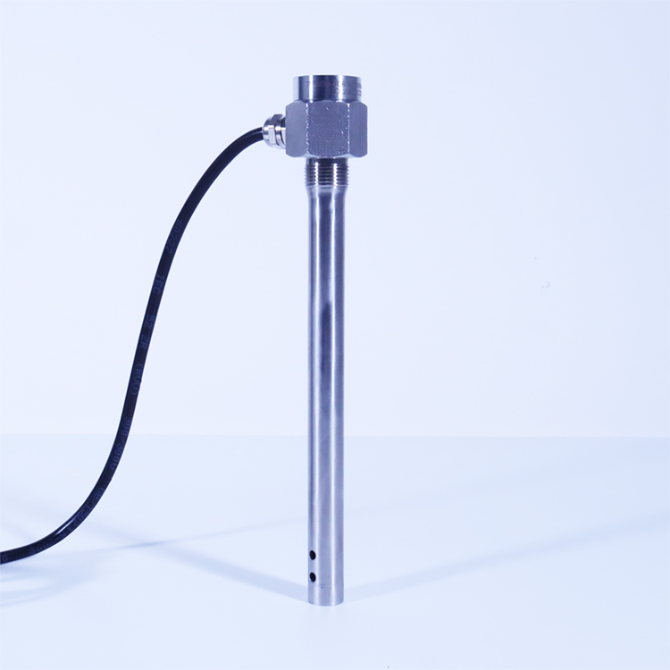
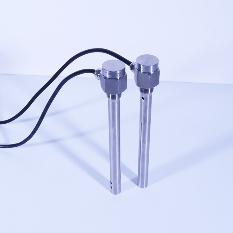
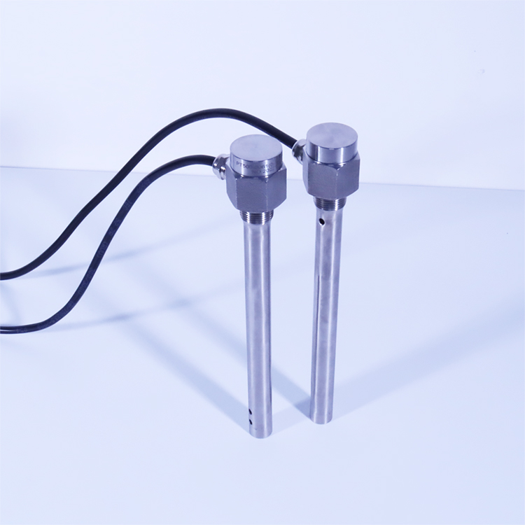
PT500-8061 oil quantity detector/capacitance level gauge is based on the principle of radio frequency capacitance measurement and adopts the fault scanning technology to dynamically analyze various parameters of the sensor in the medium, automatically and accurately compensate, and the output signal changes linearly and continuously with the change of the level height. The whole machine has no elastic parts and movable parts. It is impact resistant and easy to install. It can be installed on various occasions to accurately measure the oil level of gasoline, diesel, hydraulic oil and other weak corrosive liquids.
PT500-8061 oil level detector/capacitance level gauge is a metering level measuring instrument with high resolution and measuring accuracy. It does not need manual intervention, automatic calibration, no temperature drift, and is not affected by the change of medium. It can correctly output accurate liquid level height signal. It thoroughly solves the problem of difficult measurement of ethanol gasoline, methanol fuel and other media, and also solves the problem of measurement error caused by different oil grades and huge differences in temperature in different regions. At present, this technology is unique in China and at the international leading level.
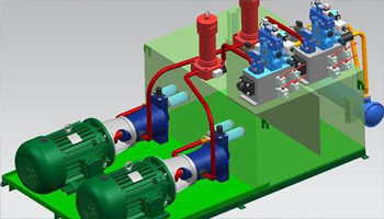
Oil pressure system
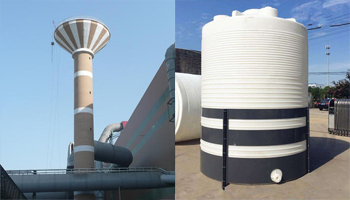
Water tank
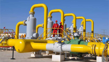
petrochemical industry
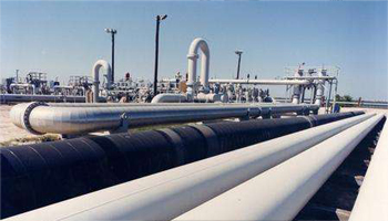
Petroleum Pipeline
PT500-8061 oil level detector/capacitive level gauge

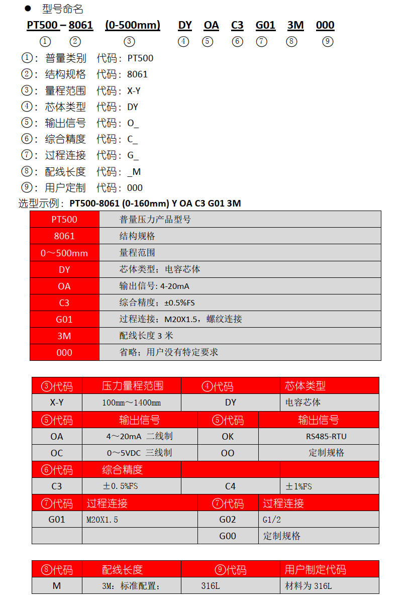
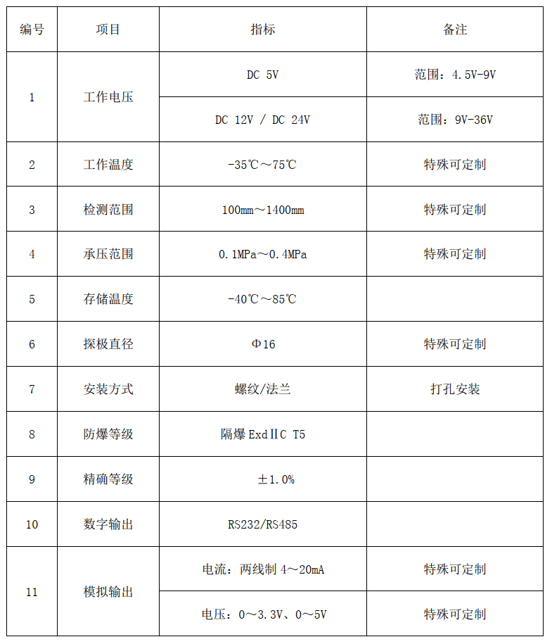
Technical parameters of PT500-8061 oil quantity detector/capacitive level gauge
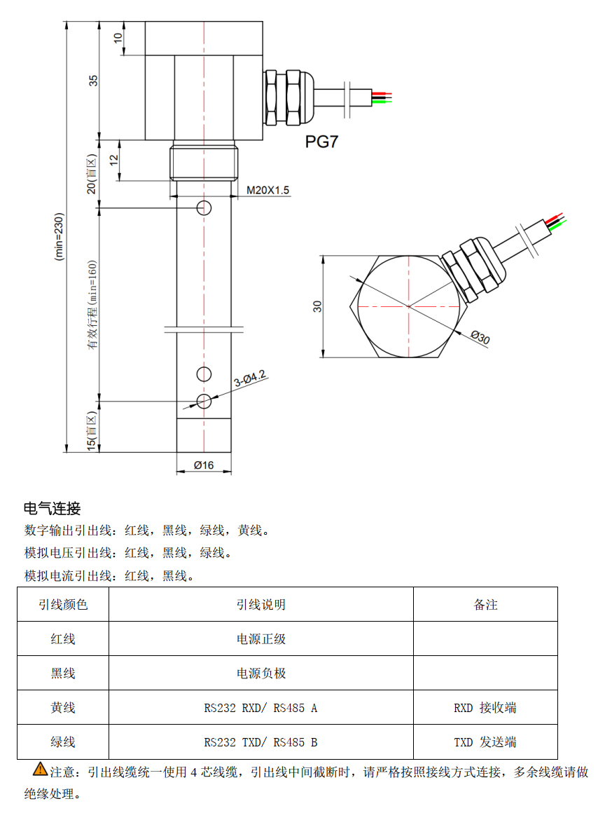
PT500-8061 oil quantity detector/capacitance level gauge structure dimension and electrical connection
PT500-8061 calibration process and installation method of oil quantity detector/capacitive level gauge
1. Standard document process:
Because the sensor adopts microcomputer control technology, the tedious manual calibration in use is eliminated. Under normal conditions, the whole machine can be directly applied to the measurement of conventional media without calibration. If calibration is required, the following operations can be performed:
Put the sensor slowly into the measured medium when it is powered on. Make the liquid level slowly rise from the lower hole of the sensor to more than one third of the measuring part of the sensor. The upper hole of the sensor is the best calibration position. Therefore, during the calibration process, make the liquid level rise to the upper hole of the sensor as much as possible. This completes the calibration of the sensor. To prevent calibration failure, this process should be operated more than twice.
2. Installation method
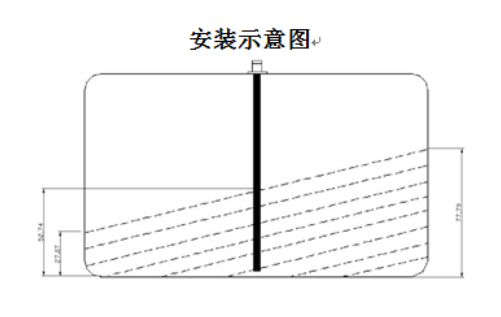
Preparations before installation:
◆ Check whether the tools used for installation are complete and whether the product accessories are complete.
◆ Before starting the operation, the fire extinguishing equipment should be placed at a convenient place to be used, in case the oil tank catches fire during the operation.
◆ Open the oil tank cover to ensure the air circulation in the oil tank.
◆ Select the installation position of the oil quantity detector at the middle part of the oil tank, clean the oil stain on the surface of the oil tank first, and pay attention not to drop the drilled debris into the oil tank during the drilling process.
◆ After the sensor is installed, cover the oil tank cap and restore it to its original state.
Conventional flange installation:
● Use a drill bit with a diameter of 22mm to drill a round hole in the center above the oil tank.
● Place the sensor flange at the selected position to ensure that the center hole of the flange is aligned with the drilled hole.
● Apply anti-oil sealant evenly around the round hole, and place sealing gasket and flange above the round hole in turn.
● Fix the flange with five 5mm drilling tail screws and remove the excess sealant at the round hole.
● Cover the sensor with an O-ring, install it in the flange round hole and fix it.
1. There can only be one RS232/RS485/0-5V (voltage)/4-20mA (current) output signal. RS485 can connect multiple sensors to work at the same time. The communication address of the connected sensors cannot be the same.
2. The installation environment of this product is complex. It is recommended to use isolated power supply and shielded cable for power supply.
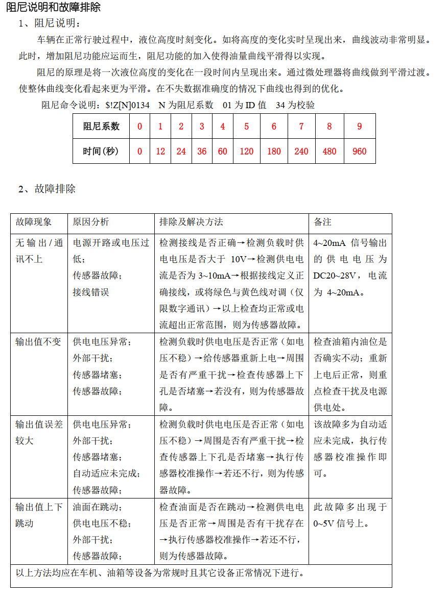
3. For the sensor of RS232/RS485 signal, when the failure of communication is eliminated, the green and yellow lines can be exchanged for testing. If the communication is successful, it indicates that it is caused by wiring error. This operation is limited to digital communication.
4. The power supply voltage of the sensor shall not exceed its normal working voltage, and the power consumption of the sensor power supply shall not be less than the power consumption of the sensor in normal operation.
5. The actual environment shall comply with the basic parameters of the sensor and shall not exceed the normal range, otherwise the sensor will be damaged and even other accidents will occur.
6. The sensor outputs the position and height signal of the measured medium. When the filter is zero, the curve formed by the output value reflects the actual change of the oil level. The output value changes with the rise or fall of the oil level. After the filter, the curve will become smooth. The larger the filter value is, the smoother the curve will be, but the oil quantity valuewill lag behind the change of the oil quantity. Therefore, the smoothness of the curve is directly proportional to the lag time (reaction time) of the oil quantity value. The factory filter value is a more suitable value set based on customer feedback and site conditions.
7. Due to the relationship between oil products, there is a certain difference between the medium used in the sensor setting and the medium used in the field. The sensor has the function of automatically adapting to multiple media, which can solve the error caused by different media. Therefore, the user should perform the sensor calibration operation before use.
Tel:0757-26619568 Fax: 0757-26619508
24-hour online technical support:13790092618
Cloud platform:www.puliangiot.com
Address:501, block 8, phase 5, Rongli tianfulai industrial city, Ronggui town, Shunde District, Foshan City